Finite Element Analysis Study of the Influence of Simulated Surgical Methods on Kinematics of a Model of the Full Cervical Spine
Gladius Lewis
DOI10.21767/2471-8173.100014
Yuxin Qi and Gladius Lewis*
Department of Mechanical Engineering, The University of Memphis, Memphis, TN 38152-3180, USA
- *Corresponding Author:
- Gladius Lewis
Professor, Department of Mechanical Engineering, The University of Memphis, Memphis, TN 38152-3180, USA.
Tel: 901 678 3266
Fax: 901 678 5459
E-mail: glewis@memphis.edu
Received date: March 01, 2015; Accepted date:March 05, 2016; Published date: March 09, 2016
Citation: Yuxin Qi, Lewis G. Finite Element Analysis Study of the Influence of Simulated Surgical Methods on Kinematics of a Model of the Full Cervical Spine . Spine Res. 2015, 2:1. doi:10.21767/2471-8173.100014
Abstract
The consensus is that degenerative disc disease (DDD), especially in its severe form, plays a key role in the etiology of a large assortment of symptomatic disorders of the spine, among which are herniation of the nucleus pulposus, discogenic pain, loss of disc height, loss of segmental mobility, development of osteophytes along the spine, myelopathy, radiculopathy, myeloradiculopathy, and traumatic instability at one or more levels .
Keywords
Overweight children; Football intervention; Bone mass; Physical fitness
Introduction
The consensus is that degenerative disc disease (DDD), especially in its severe form, plays a key role in the etiology of a large assortment of symptomatic disorders of the spine, among which are herniation of the nucleus pulposus, discogenic pain, loss of disc height, loss of segmental mobility, development of osteophytes along the spine, myelopathy, radiculopathy, myeloradiculopathy, and traumatic instability at one or more levels [1]. In the cervical spine, when any of these disorders is diagnosed as originating from DDD and the pain/discomfort is not relieved by a conservative treatment, such as physical therapy and intermittent traction [2], the usual recourse is to use a surgical modality, the most widely used of which are anterior cervical discectomy without fusion (ACD), anterior cervical discectomy followed by fusion (ACDF), and disc arthroplasty (implantation of a total disc replacement) (TDR) [3,4]. Other surgical modalities include percutaneous nucleotomy [5] and nucleus pulposus replacement [6].
Three shortcomings of the very large body of literature on finite element analysis (FEA) of models of the cervical spine are noted. First, a model of the full cervical spine (herein, defined as C0-T1, or C0-C7, or C1-T1, or C1-C7) is used in only a few studies [7-13]. Second, to the best of the present workers’ knowledge, there are no studies in which a model of the full intact cervical spine and its modification to simulate each of the three most widely used surgical method (ACD, ACDF, and TDR) was used. Third, in two of the studies in which a full cervical spine model was used, kinematic parameters were not determined [9,13]. This omission is surprising given the fact that many normal activities of daily living involve motion of the cervical spine. Furthermore, since, in many clinical reports, data on motions are given, this omission means that only limited discussion of the clinical relevance of the reported FEA results can be undertaken.
In the present FEA study, we constructed a three-dimensional (3D) solid model of the full cervical spine (C1-C7), validated it, and then used the validated model to determine the influence of each of the simulations of the three widely used surgical methods on the principal motion at each of the intersegmental locations in the model. For the simulations, DDD was taken to occur at a level that is commonly presented, namely, C5-C6 [14], and each of the applied loadings used is clinically-relevant [9,15].
Materials and Methods
Seven 3D solid models of the full cervical spine (C1-C7) were constructed: the first was of an intact, healthy spine and the others were modifications of this spine to simulate the three surgical methods studied.
Model of intact, healthy spine
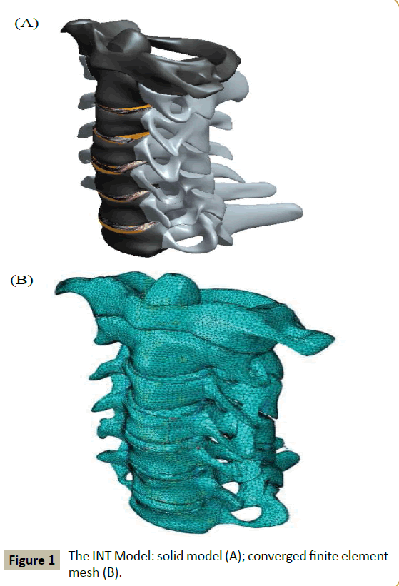
The solid model was constructed by using digitized quantitative axial computed tomography scans/images of the bony parts of the full cervical spine of a male cadaver imported from the Visible Human Project® dataset (National Library of Medicine, Bethesda, MD, USA). A 3D scanning software package (Mimics® Version 8.1; Materialise, Inc., Leuven, Belgium), a 3D medical image processing and editing software package (RapidForm® Version 2006; INUS Technology, Inc., Seoul. South Korea) and a computer-aided drawing software package (ProEngineer® Wildfire 5.0; Parametric Technology Corporation, Needham, MA, USA). These bony parts were the vertebral bodies, the posterior elements (transverse processes, pedicles, laminae, spinous processes, and facet joints), and the endplates. Constructed separately were the disc (with the annulus fibrosus and the nucleus pulposus occupying 60% and 40% of the total volume, respectively [16]) and the ligaments. The final solid model was obtained by merging the three sub-models (bony parts, discs, and ligaments) (Figure 1A).
The final solid model was meshed using an FEA software package (ABAQUS®, Version 6.13; Abaqus, Inc., Providence, RI, USA). Details of element types used for the finite element (FE) meshing and the properties of all the materials in the model are given in (Table 1). The convergence criterion used was a change of <1.5% in the rotation at C1-C2 of the model, under a loading of 1 Nm axial flexion + 73.6 N compression force, between successive changes in mesh density. Validation involved comparing the range of motion of each of the motion segments in the model, under various applied loadings, to applicable experimental results reported in the literature.
| Tissue/materiala | Element type | Elastic propertyb | Referencec |
|---|---|---|---|
| Cortical bone | 3-noded triangular general purpose shell | E11 = 9,600 MPa; E22 = 9,600 MPa E33 = 17,800 MPa; G12 = 3,097 MPa G13 = 3,510 MPa; G23 = 3,510 MPa n12 = 0.55; n13 = 0.30; n23 = 0.30 |
Rho [17]; Cowin[18] |
| Cancellous bone | 4-noded tetrahedral | E11 = 144 MPa; E22 = 99 MPa E33 = 344 MPa; G12 = 53 MPa G13 = 45 MPa; G23 = 63 MPa n12 = 0.23; n13 = 0.17; n23 = 0.11 |
Ulrich et al. [19] |
| Posteriorelements | 4-noded tetrahedral | E = 3,500 MPa; n = 0.29 |
Kumaresan et al. [20] |
| Annulus fibrosus | 4-noded tetrahedral | Ground substance: E = 4.2 MPa; n = 0.45Elastic fibers: E = 450 MPa; n = 0.30 |
Ha et al. [21] |
| Nucleus pulposus | 8-noded brick | E = 1.0 MPa; n =0.499 |
Ha et al. [21] Brolin and Halldin [22] |
| Endplates | 4-noded tetrahedral | E = 500 MPa; n =0.40 |
Yoganandan et al. [23] |
| ALL | Nonlinear tension-only spar | E = 30.0 MPa | Zhang et al. [8] |
| PLL | Nonlinear tension-only spar | E = 20.0 MPa | Zhang et al. [8] |
| ISL, LF (C1-C2) | Nonlinear tension-only spar | E = 10.0 MPa | Zhang et al. [8] |
| SSL, ISL, LF (C2-C7) | Nonlinear tension-only spar | E =1.5 MPa | Zhang et al. [8] |
| CL (C1-C3) | Nonlinear tension-only spar | E = 10.0 MPa | Zhang et al. [8] |
| CL (C3-C7) | Nonlinear tension-only spar | E = 20.0 MPa | Zhang et al. [8] |
| A1L | Nonlinear tension-only spar | E =5.0 MPa | Zhang et al. [8] |
| TL | Nonlinear tension-only spar | E = 20.0 MPa | Zhang et al. [8] |
| ApL | Nonlinear tension-only spar | E = 20.0 MPa | Zhang et al. [8] |
| Iliac crest bone graft | 4-noded tetrahedron | E = 3,500 MPa; n = 0.25 |
Natarajan et al. [24] |
| Co-Cr-Mo alloy | 8-noded brick | E = 220 GPa; n = 0.32 |
Ratner et al. [25] |
| UHMWPE | 8-noded brick | E = 1GPa; n = 0.49 |
Ratner et al. [25] |
aALL: anterior longitudinal ligament; PLL: posterior longitudinal ligament; SSL: supraspinous ligament; ISL: interspinous ligament; LF: ligamentumflavum; CL: capsular ligament; AlL: alar ligament; TL: transverse ligament; ApL: apical ligament. UHMWPE: ultra-high-molecular-weight polyethylene.
bE: modulus of elasticity; : Poisson’s ratio. 11, 22, and 33 refer to the radial, tangential, and longitudinal axes of the bone, respectively.
cThe literature references are for the values of the elastic properties.
Table 1 Element type and elastic properties of the tissues/materials in the finite element model.
Models of simulated surgically altered spines
Each of the simulated surgically altered models was obtained by modifying the solid geometry of the INT model and, then, meshing it.
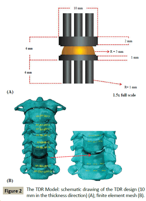
For ACD Model, the inferior endplate on the C5 vertebral body, the disc at C5-C6, the ALL at C5-C6, and the superior endplate on the C6 vertebral body were all removed. Then, the inferior surface of the C5 vertebral body and the superior surface of the C6 vertebral body were sculpted so that they fitted perfectly. These steps were consistent with the surgical method used by Nandoe- Tiwari et al. [26]. For ACDF Model, the tissues removed were the same as for the ACD Model with the exception that the empty disc space was filled with a brick-shaped graft (height and area = 100% and 85% those of the removed disc, respectively [27]). It was ensured that the posterior edge of the graft did not touch the posterior longitudinal ligament at C5-C6 and the superior and inferior faces of the graft were considered fully bonded with the inferior surface of the C5 vertebral body and the superior surface of the C6 vertebral body, respectively. These steps are consistent with a surgical procedure, namely, the Smith-Robinson method [28]. For TDR Model, the tissues removed were the same as those in ACD Model, but, in this case, the empty disc space was filled with a notional endplates-and-mobile insert TDR design (Figure 2A) ensuring that there was perfect contact between the top and bottom surfaces of the implant with the inferior surface of C5 and the superior surface of C6, respectively. In terms of materials, this notional design is comparable to four of the six TDR designs that are approved by the US Food and Drug Administration for use in clinical work, namely, Mobi-C® (LDR Spine USA, San Antonio, TX, USA), PCM® (Cervitech, Rockaway, NJ, USA), ProDisc-C® (Synthes, Inc., Philadelphia, PA, USA), and Secure®-C (Globus Medical, Audubon, PA, USA). Details of the element types used for the FE meshing and the properties of the materials are given in (Table 1).
Boundary conditions and loadings
For each of the four models (INT, ACD, ACDF, and TDR Models), the loading was applied to the superior surface of the C1 vertebral body while the inferior surface of the C7 vertebral body was fully fixed.
The applied loadings used were: 1) 1 Nm flexion moment + 73.6 N axial compression force; 2) 1 Nm extension moment + 73.6 N axial compression force; 3) 1 Nm left lateral bending moment +73.6 N axial compressive force; 4) 1 Nm right lateral bending moment + 73.6 N axial compression force; 5) 1 Nm counter-clockwise-acting (left) axial torsional moment + 73.6 N axial compression force; and 6) 1 Nm clockwise-acting (right) axial torsional moment + 73.6 N axial compression force The compression force simulates the weight of the head [9], while the magnitudes of the moments and the axial compression force are clinically-relevant [15].
Biomechanical parameters determined
Under each loading, the motion at each of the intersegmental positions (that is, at C1-C2, C2-C3, C3-C4, C4-C5, C5-C6, and C6- C7) was determined, which allowed computation of the change in that motion when a surgical-simulated model was used (ACD,ACDF, or TDR Model) compared to the value when INT Model was used.
Results
Convergence test and model validation results
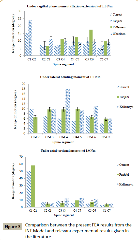
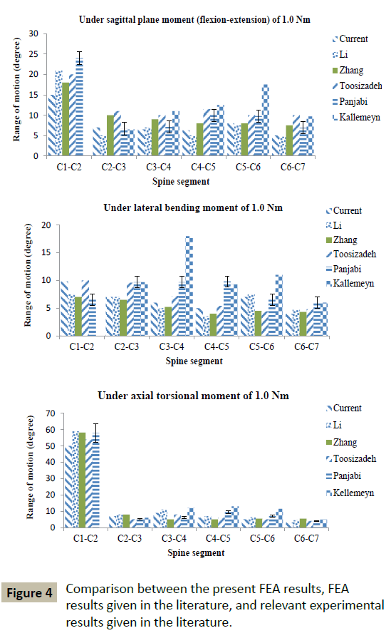
The mesh density of the converged INT model consisted of 264,301 elements and 67,033 nodes (Figure 1B). With a few exceptions, the FEA results obtained using converged INT Model are within the range obtained from experimental tests, as reported in the literature (Figure 3). Differences between some features of INT Model and those used in these experimental tests include spine section covered (C1-C7 in the present study versus C0-C7 [29], C2-T1 [30], and C2-C7 [31]) and the method and position used to apply the moments (in the present study, application of a load on the superior surface of the C1 vertebral body along an anatomical axis while the inferior surface of the C7 vertebral body was fixed in position and direction versus, for example, via a spinal gimbal and an XY table [31]). Furthermore, comparison of FEA results, reported by previous workers, to the same set of literature experimental results yield the same trends as found in the present results (Figure 4). When all of these observations were taken into account, it may be concluded that INT model was validated.
Simulated surgically altered spine models
The final mesh density of each of these models is given in (Table 2) and, as an example, the meshed finite element model of TDR Model is shown in (Figure 2B).
| Model | Final number of elements | Final number of nodes |
|---|---|---|
| INTACT | 421,160 | 89,161 |
| ACD | 413,107 | 86,868 |
| ACDF | 446,567 | 92,425 |
| TDR | 704,202 | 105,242 |
Table 2 Mesh densities of the finite element models.
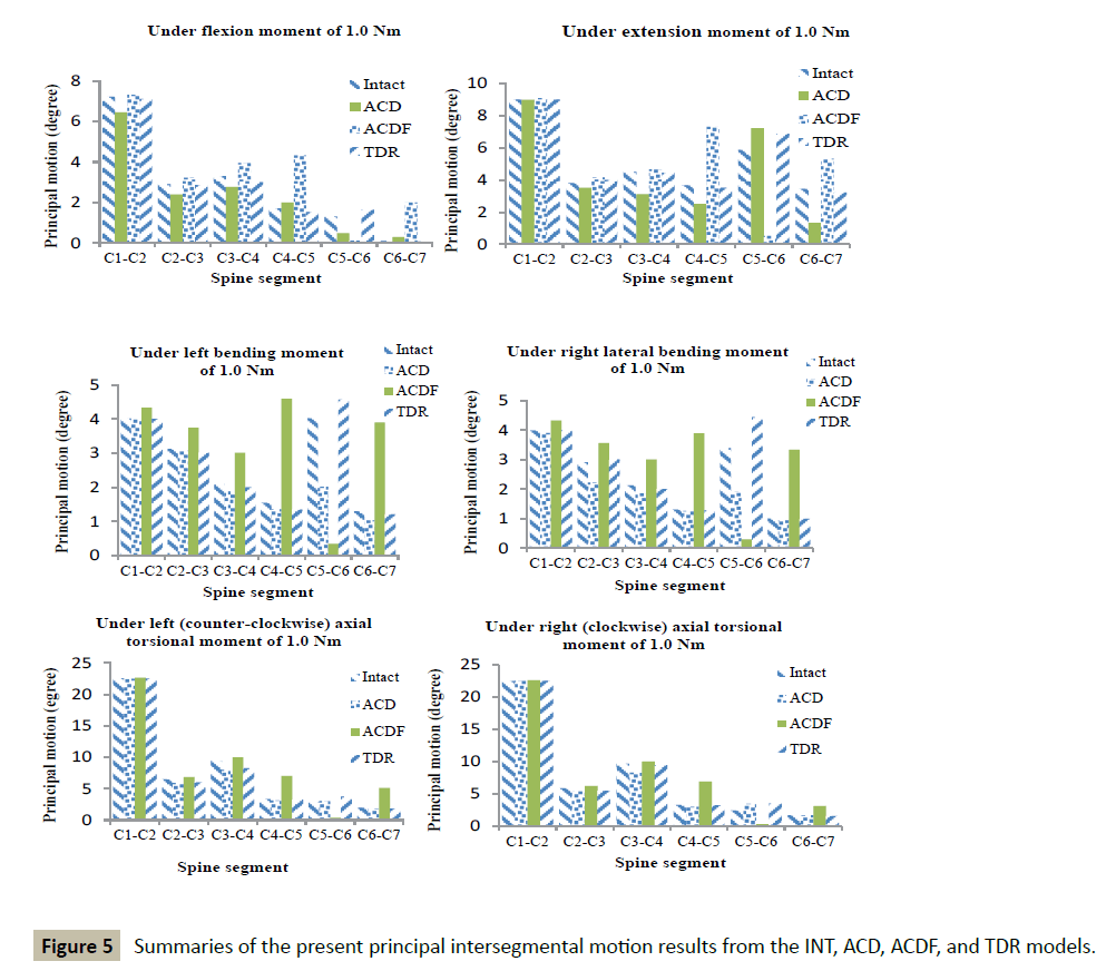
When the whole collection of results (Figure 5 and Tables 3 and 4) is considered, it is seen that the TDR Model produced the highest frequency of the smallest % changes in principal intersegmental motions (22 times out of a possible 36 times).
| Load type | Model | C1-C2 | C2-C3 | C3-C4 | C4-C5 | C5-C6 | C6-C7 |
|---|---|---|---|---|---|---|---|
| Flexion | ACD | -10.6 | -17.6 | -16.0 | 17.0 | -62.0 | 100 |
| ACDF | 1.0 | 10.6 | 19.7 | 152 | -91.0 | 200 | |
| TDR | -1.5 | -1.5 | -9.1 | -10.4 | 25.0 | -13.7 | |
| Extension | ACD | -0.1 | -7.9 | -30.7 | -31.4 | 23.2 | -61.1 |
| ACDF | 1.0 | 9.2 | 3.0 | 99.0 | -91.0 | 70.0 | |
| TDR | -0.4 | 5.0 | -1.0 | -4.0 | 17.2 | -6.0 | |
| LLB | ACD | -0.3 | -1.0 | -4.0 | -12.3 | -15.0 | -20.3 |
| ACDF | 7.8 | 20.0 | 44.0 | 197 | -91.4 | 200 | |
| TDR | -0.3 | 3.7 | -5.0 | -13 | 13.6 | -6.5 | |
| RLB | ACD | -2.0 | -23.7 | -12.2 | -3.6 | -43.0 | -6.7 |
| ACDF | 8.5 | 22.3 | 41.2 | 196 | -91.0 | 229 | |
| TDR | 0.2 | 3.0 | -5.6 | -2.0 | 31.0 | -1.4 | |
| LTM | ACD | -0.3 | -9.0 | -15.6 | -6.8 | 6.0 | -8.5 |
| ACDF | 0.5 | 5.0 | 5.6 | 110 | -86.0 | 158 | |
| TDR | -0.4 | -7.7 | -12.9 | -2.6 | 32.4 | -7.8 | |
| RTM | ACD | 0.1 | -7.5 | -14.1 | -8.9 | 42.1 | -2.0 |
| ACDF | 0.5 | 6.0 | 3.8 | 109 | -86.0 | 82.0 | |
| TDR | 0.5 | -6.0 | -2.4 | -0.1 | 30.0 | -7.8 |
aLLB: left lateral bending; RLB: right lateral bending; LTM: left (counter-clockwise) axial torsional moment; RTM: right (clockwise) axial torsional moment.
Table 3 Summary of % changes in principal intersegmental motion under different applied loadingsa.
| Loading | C1-C2 | C2-C3 | C3-C4 | C4-C5 | C5-C6 | C6-C7 |
|---|---|---|---|---|---|---|
| Flexion | ACDF | TDR | TDR | ACD | TDR | TDR |
| Extension | ACD | TDR | TDR | TDR | TDR | TDR |
| LLB | ACD | ACD | ACD | ACD | TDR | TDR |
| RLB | TDR | TDR | TDR | TDR | TDR | TDR |
| LTM | ACD | ACDF | ACDF | TDR | ACD | TDR |
| RTM | ACD | TDR | TDR | TDR | TDR | ACD |
aLLB: left lateral bending; RLB: right lateral bending; LTM: left (counterclockwise) axial torsional moment; RTM: right (clockwise) axial torsional moment.
Table 4: Summary of the models that yielded the smallest % change in principal intersegmental motion under different applied loadingsa.
Discussion
In the literature on FEA studies of models of the cervical spine, studies on comparison of the influence of the three most widely surgical methods for treating pain and problems due to DDD on kinematics and on the influence of the assigned materials used in a given TDR design on kinematics are lacking. These aspects are the subject of the present work.
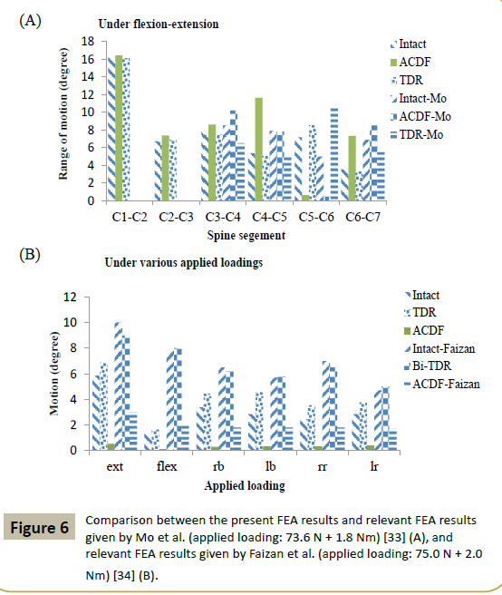
Relevant literature FEA studies are considered those that have both of the following two characteristics. First, the FEA study was of a model of the intact spine section and a minimum of two of the three surgical simulation models utilized in the present work. Second, the range of motion (ROM) results were obtained under the same types of applied loadings as were used in the present study. By this definition, to the best of the present worker’s knowledge, the only relevant literature FEA studies are those by Mo et al. [33] and by Faizan et al. [34]. Mo et al. [33] used a C3-C7 model and simulated ACDF and TDR at C5-C6 and applied a loading of 73.6 N preload + 1.8 Nm moments on C3. A comparison of Mo et al.’s ROM results and corresponding ones from the present study (Figure 6A) shows that, at C5-C6, the two sets of results for an ACDF model are similar. However, the TDR model results given by Mo et al. are higher than those obtained in the present work even though two aspects of the TDR design (type and assigned material combination) were the same in both studies. This may be a consequence of difference in the two studies with respect to dimensions of the design but, more importantly, positioning and orientation of the TDR in the C5-C6 space [35]. Fazian et al. [34] used a C3-C7 model and simulated ACDF and TDR at two levels, namely, C4-C5 and C5-C6, and applied a loading of 75.0 N + 2.0 Nm moment on C3. A comparison of Faizan et al.’s ROM results and corresponding ones from the present study (Figure 6B) shows that, at C5-C6, Faizan et al.’s ROM results for an ACDF model are higher than those obtained in the present work, with the same trend seen for the ROM results for a TDR model. These trends are to be expected given that, in the present work, surgical treatment was simulated at one level (C5-C6) but, in Faizan et al.’s study, simulation was at two levels (C4-C5 and C5-C6).
The finding that TDR Model produced the highest frequency of the smallest % changes in intersegmental motion, relative to the corresponding values when an intact model was used, is consistent with results of clinical and patient outcomes (such as Neck Disability Index score, pain score, neurological parameters, number of secondary surgical procedures, flexion-extension ROM, and number of adverse device-related events) from randomized controlled trials (RCTs) in which ACDF and an approved TDR design (Bryan® or Prestige® LP or ProDisc-C®) were compared in the treatment of symptomatic DDD at one level (C3-C4 or C4-C5 or C5-C6 or C6-C7) in patient-matched cohorts [4,36-40].
We note some limitations of the study. First, in the solid model, the facet joints were included as part of the posterior elements, rather than separate tissues. For a C5-C6 model subjected to 1.8 Nm flexion moment + 73.6 N axial compression force or 1.8 Nm extension moment + 73.6 N axial compression force, the principal motions were ∼25% greater when facet joints were include as separate entities compared to when they were included as part of the bone posterior structures [41]. Second, in the solid model, the muscles were not included. The important role played by muscle forces in spinal motions is well recognized [42]. However, this aspect is particularly important when dynamic or impact loading is applied. In the present study, the loading was quasi-static. Third, in the solid model of each of the simulated surgical methods, perfect bonding was assigned at the respective interfaces (for example, inferior surface of C5-superior surface of C6, in the case of ACD Model; and inferior surface of C5-superior surface of TDR design and inferior surface of TDR deign-superior surface of C6, in TDR Models). In other words, the simulation was for the situation that is likely to exist several weeks after surgery [3,4]. In the FEA, a Coulomb friction contact or a stick-slip contact formulation could be used to model an interface [43,44]. Fourth, the solid model was built using data taken from one person and, as such, it is unknown if the results obtained have generality. This problem could be overcome by using a parametric modeling method [45] or a parametric and patient-specific modeling method [46]. Fifth, in the FEA, the ground substance and the fibers in the annulus fibrosus (AF) and the nucleus pulposus (NP) were each taken to be linear, isotropic, elastic materials. Other material models been used for these tissues, including hyperelastic (Mooney-Rivlin) or hyperelastic (neo-Hookean) for the annulus ground substance [41], nonlinear stress-strain relationship for the annulus fibers [23], hyperelastic incompressible solid for the nucleus [47]; incompressible fluid for the NP [48]; and poroelasticity for both the AF and the NP [49]. For a C4-C6 model, subjected to 100 N compression force uniformly distributed on the superior surface of the C4 vertebral body, in some tissues, such as the inferior endplate at C5, the mean von Mises stress was markedly sensitive to the constitutive model used for the AF and NP, whereas other tissues, such as the cancellous bone at C4, showed moderate sensitivity [41]. Since the present work is a parametric study, each of these the limitations applies to all the models; as such, the trends in changes in intersegmental motions and, hence, our conclusions are valid.
Conclusion
For a model of the full cervical spine (C1-C7), with simulated surgical treatment for problems due to severe DDD at C5-C6, subject to clinically-relevant loading, the highest frequency of the smallest % changes in principal intersegmental motions was obtained when TDR was simulated. This finding is in consonance with the results of many RCTs in which TDR was compared to ACDF in several patient-matched cohorts.
Conflict of interest
No benefits of any form have been or will be received from a commercial party related directly or indirectly to the subject of this manuscript.
References
- Adams MA, Roughley PJ (2006)What is intervertebral disc degeneration, and what causes it? Spine31:2151-2161.
- Engquist M,Löfgren H, Öberg B, Holtz APeolsson et al. (2015)Factors affecting the outcome of surgical versus nonsurgical treatment of cervical radiculopathy: a randomized, controlled study. Spine40:1553-1563.
- Mobbs RJ, Rao P, Chandran NK (2007) Anterior cervical discectomy and fusion: analysis of surgical outcome with and without plating.J Clin Neurosci 14: 639-642.
- Gornet MF, Burkus JK, Shaffrey ME, Argires PJ, Nian H, et al. (2015)Cervical disc arthroplasty with PRESTIGE LP disc versus anterior cervical discectomy with fusion: a prospective, multicenter investigational device exemption study. J Neurosurg Spine 23:558-573.
- Hellinger S (2008) Minimal invasive surgery of the cervical disc-nonendoscopic percutaneous cervical laser decompression and nucleotomy and selective percutaneous endoscopic cervical nucleotomy using radiowave.Internet J Minimal Invas Spinal Technol 2.
- Donkersloot P (2009) Nucleus replacement with the DASCOR disc arthroplasty system: two-year follow-up results of the European multicenter clinical studies.Surg Neurol 71:140-141.
- Zhang QH, Teo EC, Ng HW (2005)Development and validation of a C0-C7 FE complex for biomechanical study.J Bimech Eng 127:729-736.
- Zhang QH, Teo EC, Ng HW, Lee VS (2006) Finite element analysis of moment-rotation relationships for human cervical spine.J Biomech39:189-93.
- Tchako A, Sadegh A (2009) Stress changes in intervertebral discs of the cervical spine due to partial discectomies and fusion.J Biomech Eng 131:051013-1-051013-11.
- Li Y, Lewis G (2010) Association between extent of simulated degeneration of C5-C6disc and biomechanical parameters of a model of the full cervical spine: a finite element analysis study. J Appl BiomaterBiomech8:191-199.
- Li Y, Lewis G (2010) Influence of surgical treatment for disc degeneration disease atC5-C6 on changes on some biomechanical parameters of the cervical spine. Med Eng Phy32:595-603.
- Li Y, Lewis G (2011) Conventional versus minimally-invasive cervical discectomy for treatment of severe degenerative disease at C5-C6; a biomechanical comparison using a model of the full cervical spine and finite element analysis. J Biomed Sci Eng 599-608.
- Bannerjee PS, Pradhan R, Roychowdhury A, Karmakar SK (2015) Investigation of stresses developed in natural and implanted human cervical spine by finite element method.J Advan Mater Dent Sci 31:9-18.
- Samartzis D, Shen FH, Lyon C, Phillips M, Goldberg EJ, et al. (2004)Does rigid instrumentation increase the fusion rate in one-level anterior cervical discectomy and fusion?Spine J 4:636-643.
- Rohlmann A, Graichen F, Bender A, Kavser R, Bergmann G (2008) Loadson a telemetrized vertebral body replacement measured in three patients within the first postoperative month.Clin Biomech23:147-158.
- Smit TH (1996)The mechanical significance of the trabeculae bone architecture in a human vertebra, Ingenieur thesis, Technical University of Hamburg, Hamburg, Germany.
- Rho RY.Ultrasonic methods for evaluating mechanical properties of bone, In: An YH, Draughn RA (Eds). Mechanical testing of bone and bone-implant interface, Boca Raton, FL: CRC Press; 2000.
- Cowin SC (2011)Bone mechanics handbook, 2nd ed.Boca Raton.
- Ulrich D, Rietbergen B, Laib A, Ruegsegger P (1999)The ability of three-dimensional structural indices to reflect mechanical aspects of trabecular bone.Bone5:55-60.
- Kumaresan S, Yoganandan N, Pintar FA (1997) Finite element analysis of anterior cervical spine interbody fusion.Bio-Med Mater Eng 7:221-230.
- Ha SK (2006)Finite element modeling of multi-level cervical spinal segments (C3-C6) and biomechanical analysis of an elastomer-type prosthetic disc. Med Eng Phys28:534-41.
- Brolin K, Halldin P (2004) Development of a finite element model of the upper cervical spine and a paramter study of ligament characteristics. Spine 29:376-385.
- Yoganandan N, KumaresanSC, Voo L, Pintar FA, Larson SJ (1996) Finite element modeling of the C4-C6 cervical spine unit.Med Eng Phys16:569-574.
- Natarajan RN, Chen BH, An HS, Andersson GB (2000)Anterior cervical fusion: a finite element model study on motion segment stability including the effect of osteoporosis.Spine 25:955-961.
- Ratner BD, Hoffman AS, Schoen FJ, Lemond JE (2004) Biomaterials Science: An Introduction to Materials in Medicine (2ndedn); Elsevier Academic Press, San Diego, CA, USA.
- Nandoe-Tiwari RDS, Bartels RHMA, Peul WC (2006) Long-term outcomes after anterior cervical discectomy without fusion.Eur Spine J 16:1411-1416.
- Denoziere G, Ku DN (2006)Biomechanical comparison between fusion of two vertebrae and implantation of an artificial intervertebral disc. J Biomech39:766-75.
- Smith GW, Robinson RA (1958)The treatment of certain cervical-spine disorders by anterior removal of the intervertebral disc and interbody fusion.J Bone Joint Surg 40:607-624.
- Panjabi MM, Crisco JJ, Vasavada A, Oda T, Cholewicki J, et al. (1984)Mechanical properties of the human cervical spine as shown by three-dimensional load-displacement curves. Spine 26:2692-2700.
- WheeldonJA, Pintar FA, Stephanite K, Yoganandan N (2006) Experimental flexion/extension data corridors for validation of finite element models of the young, normal cervical spine. J Biomech39:375-380.
- Kallemeyn N, Gandhi A, Kode S, Shivanna K, Smucker J,et al. (2010) Validation of a C2-C7 cervical spine finite element model using specimen-specific flexibility data. Med Eng Phy32:482-489.
- Toosizadeh N, Haghpanahi M (2011) Generating a finite element model of the cervical spine: Estimating muscle forces and internal loads. Scientia Iranica18:1237-1245.
- Mo ZJ, Zhao YB, Wang LZ, Sun Y, Zhang M, et al. (2014) Biomechanical effects of cervical arthroplasty with U-shaped disc implant on segmental range of motion and loading of surrounding soft tissue. Eur Spine J 23:613-621.
- Faizan A, Goel VK, Biyani A, Garfin SR, Bono CM (2012) Adjacent level effects ofbi level disc replacement, bi level fusion and disc replacement plus fusion in cervical spine-a finite element based study. Clin Biomech27:226-33.
- Galbusera F, Anasetti F, Bellini CM, Costa F, Fornari M (2011) The influence of axial, antero=posterior and lateral positions of the center of rotation of a ball-and-socket disc prosthesis on the cervical spine biomechanics.Clin Biomech25:397-401.
- Rina J, Patel A, Dietz JW, Hoskins JS, Trammell TR, et al. (2008) Comparison of single-level cervical fusion and a metal-on-metal cervical disc replacement device. Am J Orthop37:71-77.
- Muheremu A, Niu X, Wu Z, Muhanmode VY, Tian W (2015) Comparison of the short- and long-term treatment effect of cervical disk replacement and anterior cervical disk fusion: a meta-analysis.Eur J Orthop Surg Traumatol25:87-100.
- Janssen ME, Zigler JE, Spivak JM,Delamarter RB, Darden II BV, et al. (2015)ProDisc-C total disc replacement versus anterior cervicak discectomy and fusionfor single-level symptomatic cervical disc disease.J Bone Joint Surg Am 97:1738-1747.
- Aragones M, Hevia E, Barrios C (2015)Polyurethane on titanium unconstrained disc arthroplasty versus anterior discectomy and fusion for thetreatment of cervical disc disease: a review of level I-II randomized clinical trials including clinical outcomes.Eur Spine J 24:2735-2745.
- Yan Q, Liang F, Xia Y, Jin C (2015)A meta-analysis comparing total disc arthroplasty with anterior cervical discectomy and fusion for the treatment of cervical degenerative diseases.Arch Orhop Trauma Surg 2337-2340.
- Li Y, Lewis G (2009) Influence of the constitutive material behavior model assigned to the annulus fibrosus and the nucleus pulposus on the biomechanical performance of a model of the cervical spine: a finite element analysis study.J Mech Med Biol 10:151-166.
- Kettlera A, Hartwigb E, Schultheib M, Claesa L, Wilkea H (2002) Mechanically simulated muscle forces strongly stabilize intact and injured upper cervical spine specimens. J Biomech35:339-346.
- Adam C, Pearcy M, McCombe P (2003) Stress analysis of interbody fusion-finite element modeling of intervertebral implant and vertebral body. Clin Biomech18:265-272.
- Kluess D, Souffrant R, Mittelmeier W, Wree A, Schnitz K-P, et al. (2009)A convenient approach for finite element-analyses of orthopaedic implants in bone contact: modeling and experimental validation. Comput Meth Prog Biomed 95:23-30.
- Haghpanahi M, Javadi M (2012) A three dimensional parametric model of whole lower cervical spine (C3-C7) under flexion, extension, torsion and lateral bending. Sci Ira 19:142-150.
- Laville A, Laporte S, Skalli W (2019) Parametric and subject-specific finite element modeling of the lower cervical spine, Influence of geometrical parameters on the motion patterns. J Biomech42:1409-1415.
- Perez del Palomar A, Calvo B, Doblare M (2008) An accurate finite element model of the cervical spine under quasi-static loading. J Biomech41:523-531.
- Kumaresan S, Yogananadan N, Pintar FA, Maiman DJ, Goel VK (2001)Contribution of disc degeneration to osteophyte formation in the cervical spine: a biomechanical investigation.J Orthop Res 19:977-984.
- Jones AC, Wilcox RK (2008) Finite element analysis of the spine: towards a framework of verification, validation and sensitivity analysis.Med Eng Phys30: 1287-1304.
Open Access Journals
- Aquaculture & Veterinary Science
- Chemistry & Chemical Sciences
- Clinical Sciences
- Engineering
- General Science
- Genetics & Molecular Biology
- Health Care & Nursing
- Immunology & Microbiology
- Materials Science
- Mathematics & Physics
- Medical Sciences
- Neurology & Psychiatry
- Oncology & Cancer Science
- Pharmaceutical Sciences
